
Flanged Floating Ball Valve
Flanged Floating Ball Valve is selected for asme flanged process piping where bolted removal and standard flange connections are required. A flanged floating ball valve combines a floating ball-and-seat arrangement with RF or other specified flange ends. It is widely used in process and utility piping because it can be removed from the line without cutting the pipe and can be matched to the project flange standard and pressure class.
Flanged Floating Ball Valve for industrial valve projects.
A flanged floating ball valve combines a floating ball-and-seat arrangement with RF or other specified flange ends. It is widely used in process and utility piping because it can be removed from the line without cutting the pipe and can be matched to the project flange standard and pressure class.
When to select this design
ASME flanged process piping where bolted removal and standard flange connections are required.
Choose this design when standard flanged installation and easy line removal are more important than welded-end integrity.
Typical applications
- Refining utilities
- Process plants
- Terminal piping
- Water and industrial service
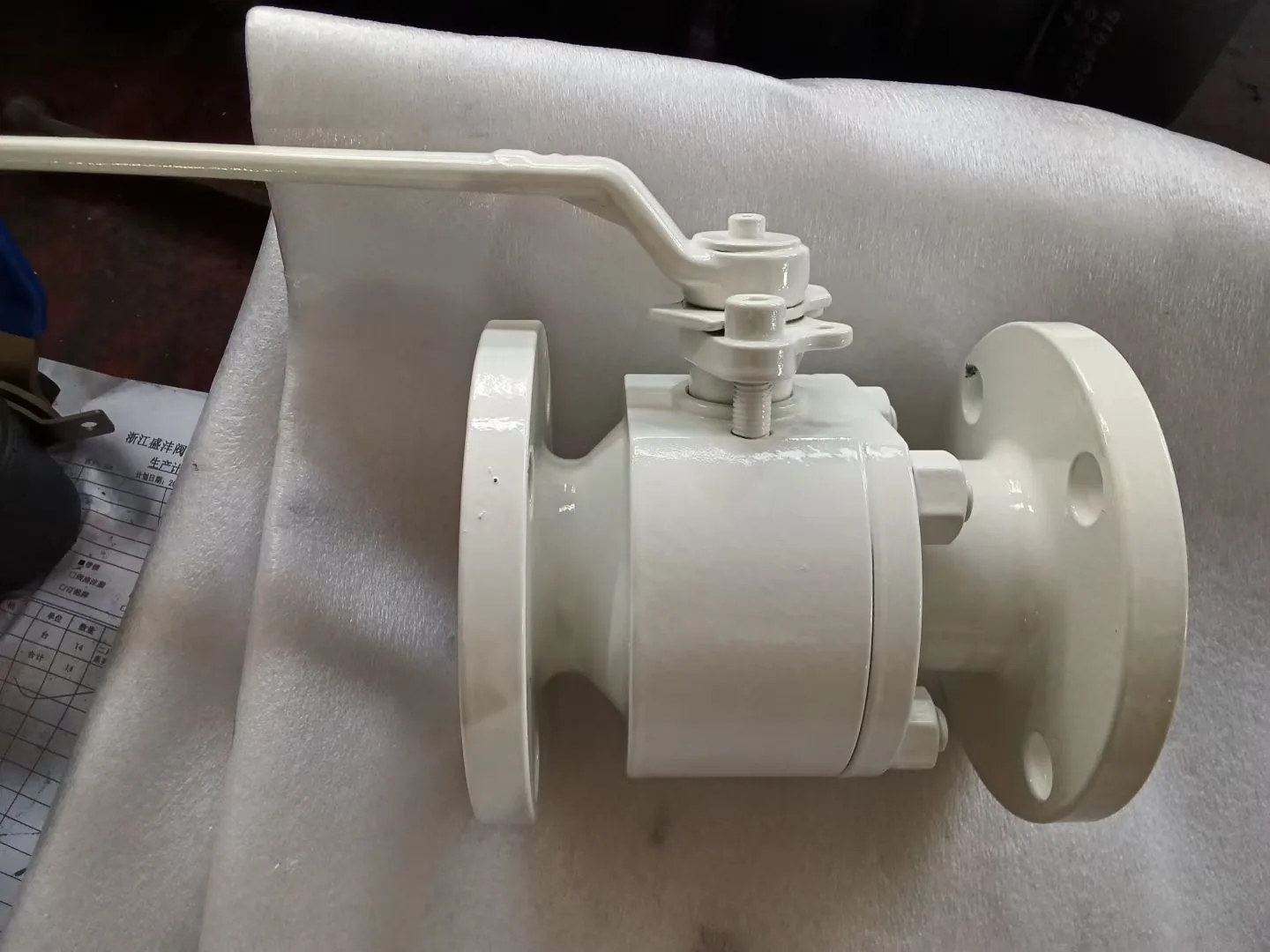
Flanged Floating Ball Valve: design points to confirm.
This is a specific valve construction. Final size, class, material and seat combinations depend on the approved datasheet and design calculation.
| Body construction | Floating ball construction with flanged end connections provides a removable line valve for many process systems. Body style can vary by size and pressure class, but flange compatibility is a primary selection input. |
|---|---|
| Seat & sealing | Seat selection controls pressure-temperature capability and operating torque. PTFE, reinforced PTFE, nylon, PEEK or other materials may be considered according to the actual design and service. |
| End connection | Confirm RF or other flange facing, ASME flange standard, pressure class, drilling and face-to-face dimensions. Mating flange compatibility should be checked before final approval. |
| Engineering focus | The floating ball creates seat loading from line pressure, so practical size/pressure range and torque must be checked rather than assuming one design covers all classes. |
| Material selection | WCB, low-temperature carbon steel or stainless steel body materials may be considered depending on piping class. Trim and soft parts should be specified separately. |
| Testing & inspection | Include shell/seat test standard, fire-safe and emission requirements where applicable, plus dimensional checks for flange and face-to-face compliance. |
Engineering considerations for Flanged Floating Ball Valve.
Construction and maintenance
Floating ball construction with flanged end connections provides a removable line valve for many process systems. Body style can vary by size and pressure class, but flange compatibility is a primary selection input.
Seat, sealing and torque
Seat selection controls pressure-temperature capability and operating torque. PTFE, reinforced PTFE, nylon, PEEK or other materials may be considered according to the actual design and service.
Piping and installation
Confirm RF or other flange facing, ASME flange standard, pressure class, drilling and face-to-face dimensions. Mating flange compatibility should be checked before final approval.
What to verify before approving the technical offer.
Engineering risk
The floating ball creates seat loading from line pressure, so practical size/pressure range and torque must be checked rather than assuming one design covers all classes.
Materials and traceability
WCB, low-temperature carbon steel or stainless steel body materials may be considered depending on piping class. Trim and soft parts should be specified separately.
Inspection and testing
Include shell/seat test standard, fire-safe and emission requirements where applicable, plus dimensional checks for flange and face-to-face compliance.
Send the valve datasheet together with the piping class and project valve, material, testing and coating specifications. Missing design inputs should be clarified rather than assumed.
Other Floating Ball Valves configurations.
Compare related designs by construction, pressure class, temperature range and service conditions.
Choose this design when compact construction matters more than full body disassembly for maintenance.
Compare 2-Piece Floating Ball Valve →Choose this design when maintenance access and welded or threaded end options are a priority.
Compare 3-Piece Floating Ball Valve →Return to the Floating Ball Valves range to compare all configurations.
Back to Floating Ball Valves Range →Continue the technical selection.
Use these pages to check pressure class, material, standard and end-connection requirements against this valve design.
Flanged Floating Ball Valve FAQ
What is a flanged floating ball valve?
A flanged floating ball valve combines a floating ball-and-seat arrangement with RF or other specified flange ends. It is widely used in process and utility piping because it can be removed from the line without cutting the pipe and can be matched to the project flange standard and pressure class.
Where is a flanged floating ball valve commonly used?
Typical applications include Refining utilities, Process plants, Terminal piping, Water and industrial service. Final suitability depends on the actual service medium, pressure, temperature and project specification.
What information is needed to quote a flanged floating ball valve?
Provide size, quantity, pressure class, body and trim materials, seat material, end connection, design pressure and temperature, media, operation, design standard, fire-safe/emission requirements, testing, coating and documentation scope.
How is a flanged floating ball valve different from other floating ball valve designs?
Choose this design when standard flanged installation and easy line removal are more important than welded-end integrity.
Technical documents for project review.
For technical evaluation, request the applicable product documents and inspection records for the offered valve configuration.
Product Photos
Additional finished-valve, nameplate and component photos are available for the selected valve configuration.
GA Drawing / Datasheet
GA drawings and datasheets are prepared for the selected size, pressure class and valve configuration.
Testing & Inspection Records
Inspection documentation can include pressure testing, dimensional inspection, PMI, NDE/NDT and coating records as required by the project.